Whenever you’re dealing with a hydraulic system you always get asked, “What is your systems pressure and flow rate?” or, “Why is pressure and flow so important?”
For our discussion, let’s talk specifically about fixed displacement components. There are variable displacement pumps and motors used in equipment today but to make these concepts easier to digest I will refer to fixed displacement components. Examples of fixed displacement components are gear pumps, gear motors, and hydraulic cylinders. Pressure and flow are the main variables when working with fluid power systems. Let’s look closer at flow rate.
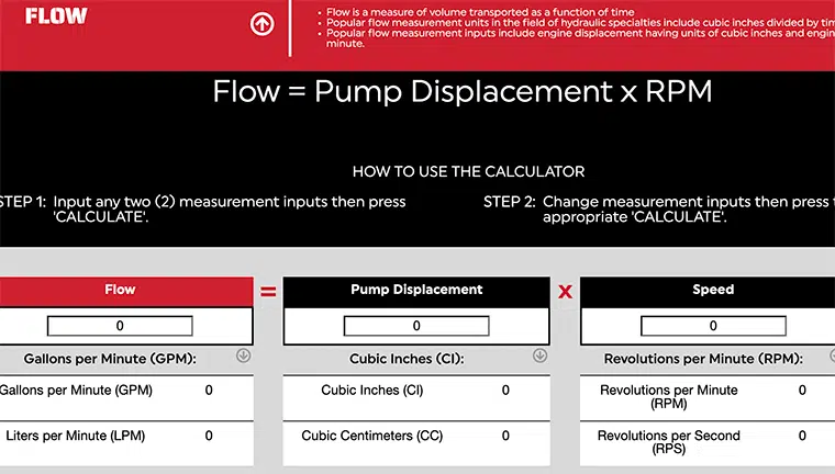
What Is Flow Rate?
 In the USA we usually measure flow in gallons per minute. In a fixed displacement pump system, the flow rate is directly related to the speed of the pump. The higher the flow rate the faster the cylinder or motor will move.
Fixed displacement hydraulic motors require a fixed volume of oil to cause the shaft to turn 1 revolution. This volume is referred to the motors displacement, usually measured in cubic inch displacement (CID) or cubic centimeter (CC). If you supply the motor with 100 times its CID every minute, it will turn 100 RPM. Speed up the flow rate and motor will go faster, slow it down and the motor will turn slower.
Because of the differences in units of measure (gallons, inches, cubic inches, etc.) we have equations to help with the conversions. For example, a motor with a 3 CID displacement turning @ 1,000 RPM requires 3,000 cubic inches of oil flow every minute (3×1,000=3,000). To convert this to gallons we divide 3000 cubic inches by 231 (cubic inches per gallon). 3000/231=12.99 gallons per minute (round up to 13 GPM). Making the motor smaller will increase the speed, and making it larger will decrease the speed given the same flow rate.
Flow Implications
There are some flow implications for tubes and hoses that need to be considered. Oil flowing through a tube or hose must move along the conductor. As the oil moves, it contacts the inside of the conductor causing friction. To overcome the friction, we need to generate pressure to cause the oil to move. If you look at a 100’ length of hose and measured the pressure at each end, the pressure at the downstream end will be lower than the upstream end. We refer to the difference as the back pressure.
Pressure drop due to back pressure is lost and ultimately converted into heat. Let’s look at a simple example from earlier.
What size hose should I use for the 13 GPM flow from the earlier motor example? There are many ways to evaluate hose diameter for a given flow rate. I prefer to use oil velocity. As you push the oil through a smaller and smaller hose the oil must flow faster and faster to maintain the flow rate. As you force the oil to move faster the back pressure increases because of the increased friction.
For this example, here are is the oil velocity in feet per second for the common hose sizes.
- ¼” Hose – 85 fps
- 3/8” Hose – 38 fps
- ½” Hose – 21.24 fps
- 5/8” Hose – 13.6 fps
- ¾” Hose – 9.5 fps
- 1” Hose – 5.31fps
- 1-1/4 Hose – 3.40 fps
There are some rules of thumb for oil velocity
- Working hoses (pressure lines) – 15-20 fps
- Return Hoses – 10 fps
- Suction Hoses – 4 fps
For this example, I would recommend 5/8 hose for the working lines and ¾ hose for the return lines. The suction line supplying the pump will need to be at least 1-1/4”. Suction lines are larger to prevent the pump from cavitating.
For the pressure line feeding the motor I would use a 5/8 hose. If 5/8 is not available ¾” or ½” would work. Know that ½ will have a higher pressure drop and cost more in fuel or electricity than the ¾ hose. ¾” hose cost more for the materials. How much available pressure you have can also play into the decision. If you are running up against the pressure rating for your pump the larger hose will help you save some pump pressure. Where ½ may have a slightly higher pressure drop using ¼” hose will have an extremely high pressure drop and could cause your system to fail.
Working With Cylinders
When working with cylinders, speed refers to the rate the cylinder rod extends or retracts. This is typically referred to in inches per minute (IPM). The speed the rod will extend is related to the area of the piston the oil is pushing against. For a 3” bore cylinder the area is 7.07 cubic inches. We’ll discuss how to calculate that in a minute.
For this example, our pump flow is 1 GPM. We calculate the IPM by calculating the volume needed to displace the cap end of cylinder. To do this we need to know the Stroke of the cylinder, in this case 12”. The cubic Inches of oil needed to displace the cylinder is 7.07 cu/in * 12 inches of stroke (7.07 * 12) = 84.84 cubic inches. To keep things simple, I like to convert GPM to cubic inches per second. (1 GPM / 231) /60 = 3.85 cu inches per second.
Now if we divide 84.84 cubic inches /3.85 we will get the number of seconds to extend the cylinder 84.84/3.85= 22 seconds to extend 12 inches. Now we can get an inches per second rate. 12 / 22 = .545 inches per second. Converting inches per second to inches per minute you multiply by 60 (.545 * 60 = 32.7 inches per minute)
The larger the bore of the cylinder the slower it will extend, If the bore is made smaller, the cylinder will move faster given the same flow rate. There are many different types of cylinders:
- single acting
- double acting
- telescopic
- single rod
- double rod
- and so on…
The formulas are applied differently for different types of cylinders. Understanding the changes in area are critical to correctly predicting cylinder speeds.
About Hydraulic Pumps
Before we discuss pressure, we first need to understand that hydraulic pumps do not generate pressure.
Hydraulic pumps generate flow and tolerate pressure. The pressure comes from resistance to the oil flow. For example, a hydraulic cylinder that is not connected to anything will extend and retract a cylinder at low pressure. The pressure measured at the pump is what is required to overcome the seal friction of the cylinder and back pressure from the oil flowing through the hoses and valves.
Hydraulic components need to be protected from pressures above there designed capability. It is very important that a hydraulic system has a way of relieving the pressure should it go higher than the components are designed to tolerate. In a simple circuit the device that does this is typically a relief valve. It allows oil to flow back to tank if the maximum pressure setting is exceeded. This is done to protect the components. Without a relief valve the components in the system will attempt operate at the higher pressure, resulting in damage or failure of the component.
With hydraulic motors and pressure, we are looking at the torque the motor can handle. In the U.S., torque is typically measured in foot pounds (ft/lbs) or inch pounds (in/lbs). Torque is the unit of measure for defining the force on a shaft. Think about driving in a screw with a screwdriver. As the screw goes deeper into the material the force required to keep in moving increases. We define that force as torque. With a rotating motor shaft, the torque is transmitted into the motor through the shaft and makes the hydraulic pressure increase to keep the motor rotating. This is the resistance to flow that causes the pressure to increase. Given a fixed displacement the higher the torque at the shaft the higher the pressure needed to keep in moving. If the torque on the shaft is constant the hydraulic pressure needed will decrease if the motor displacement is increased, conversely if the motor is made smaller the pressure will increase. As we looked at earlier there is also change in RPM if the flow rate is constant.
How Hydraulic Cylinders Work
 Let’s look at what happens when we ask a hydraulic cylinder to do some work. We need to understand how the size of the cylinder relates to the hydraulic pressure. A cylinder’s job is to convert pressure energy into force energy. In this example the formula we need is Force = Area * PSI.
Hydraulic cylinders are listed by their diameter, so we need to calculate area from diameter.
Area = Diameter * Diameter * .7854. (there are other formulas, this is the one I use)
For example, let’s use a 3” hydraulic cylinder. Using the formula to calculate area the cylinder has an area of 7.07 cubic inches. (3x3x.7854 = 7.07 cubic Inches area)
Let’s say we need to lift 15,000 lbs using this 3” cylinder, we can predict the system PSI with the formulas above. We know force (15,000 lbs) and area (7.07 cu/in) using some simple algebra we can rearrange the force formula to PSI = Force / Area (15,000 / 7.07 = 2,122 PSI)
Using a 3” cylinder I need 2,122 PSI to lift the load. The pump pressure will be higher because of seal friction and system back pressure. Probably closer to 2,250 PSI depending on hose size and valving selected.
Let’s take look at what happens if we change the diameter of the cylinder to 2.5 inches.
The cylinder area is 4.91 cu/inch (2.5*2.5*.7854)
The pressure needed to lift the load is 3,055 PSI (15,000#/4.91)
We made the area smaller and the pressure to lift the load went up proportionally. The same thing is happening with the extending speed of the cylinder. At the same flow rate, the 2.5” cylinder extends faster than the 3” cylinder because it takes less oil to displace the 2.5” cylinder.
The inverse happens if we were using a 3.5” Cylinder. Area = 9.62 cu/in (3.5*3.5*.7854)
Pressure to lift the cylinder will be 1,560 PSI (15,000#/ 9.62 cu/in)
The PSI required went down and extend time will increase.
Summary
From the examples we looked at you can see that flow rate relates to the speed of your components. Increasing flow rate will make cylinders extend and retract faster and make motors run at higher RPM. Pressure is a reaction to the force required to move the load. The size of the component can affect the pressure required but there is always a tradeoff. Lower pressure typically means larger components resulting in slower speeds
Important Reminders
When working with components in a hydraulic system always be aware of the pressure rating of the components. If the system will operate at 2500 PSI the relief will need to be set higher, 2650-2800 PSI. All components used on the pressure side of the circuit need to be rated for higher PSI than the relief valve setting. This includes the pump, directional control valves, hoses, adapters, cylinders, motors, pressure filters etc.
Items on the return side of the system can be rated for lower pressures because the PSI in that portion of the system stays relatively low. This is the return filter, cooler, tank, return hoses and adapters. Selecting components with the correct pressure rating will extend the life of your hydraulic system.